Charging the batteries during braking
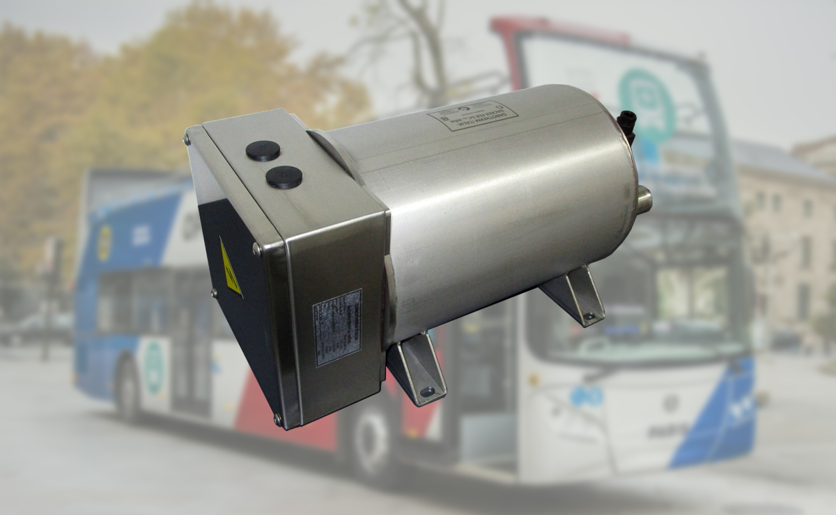
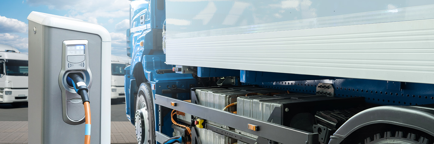
The energy transition from fossil fuel to renewable energy is the driving force for changing combustion engines to electrical drive trains for Bus & Truck industry. The power convertors on the vehicles allow to charge the batteries during braking. Next to the pneumatic brake system this is considered as the second brake. For safety reasons, the vehicle must have a dual brake system, even when the batteries are fully charged. For this reason brake resistors are used in Buses & Trucks. This paper describes the selection of brake resistors in electrical vehicles.
Electrical vehicles are the future. Even the skeptical critics who state the majority of all electrical energy comes from fossil fuel sources should be aware that in the future all fossil based energy resources will be replaced by sustainable energy sources.
Principle
Whether it is a passenger car or a big truck or bus, they all have the same principle. Electrical energy, captured in a battery, powers the vehicle. When the vehicle has to brake, the kinetic energy is recaptured and fed back into the battery. It is important to know the condition of the battery. If the battery is fully charged, no braking energy can be returned. The manufacturer of the vehicle as well as the driver must be aware of this. If the bus or truck does not have other means to dissipate excess energy, the speed of the vehicle might be limited so the mechanical brakes can cope with the braking. When the battery (capacity) allows to accept braking energy, the speed of the vehicle can be increased.
Another way of handling this is not to fully charge the battery when the vehicle leaves the terminal. This might be considered a waist of the battery capacity and it limits the driving range.
Brake resistors
A solution is the usage of an electrical brake that can dissipate any excessive energy in case the battery does not allow to accept charge. An electrical brake, basically a resistor, is maintenance free and there is no wear (when correctly dimensioned). It is very reliable and, compared to battery capacity, cost effective. Important is to understand the braking pattern of the vehicle. Urban buses have different braking patterns than coaches. This also applies to garbage trucks or excavation machines. Also the track is a factor. If the bus stays on flat roads, braking is less compared to driving in the mountains. It is important to consider this when defining the different energy/power levels. Over-engineering will result in a bigger and more expensive design. Under-engineering would jeopardize traffic. A good risk analysis can help defining the set of parameters the braking system has to fulfil.

Short-braking, long-braking and heating
In cold climates, particularly in buses for public transport, the passenger compartment is heated before the vehicle leaves the terminal. The heating system is switched on half an hour before departure and the energy comes from the grid (so it is not consuming from the battery). For this application, the brake resistor is used to heat up the water circuit to transport the heat to the passengers compartment. Heating power ranging from 30 – 60kW is quite normal. Pre-heating the bus is done once a day.
When the truck or bus gets to the motorway, the braking power can be very high. 200 – 300kW during several seconds is normal. These braking pulses can come quite often, so cycle times can be short. Additional, there can be the down-hill test where the bus or truck has to drive down a hill of a predefined height and distance at constant speed only using the resistive brake system. After the test the resistor must still be in working condition. Such braking will not happen often and it might only be needed to comply with legislation (homologation).
Selecting a brake resistor
From the three different load patterns as described above, the resistor can be selected. The start is the general overview where for each type of load the maximum values are defined. For all load patterns a thermal simulation can be made. The thermal simulation is based on the thermal model of the brake resistor. Having the thermal model of the resistor brings great advantages to the engineers. It saves on engineering and testing time and leads to the correct size for the resistor. The thermal model is a translation from the physical properties to the thermal properties. From the thermal simulation the internal temperatures of the brake resistor elements are calculated. When the different material temperatures are within design parameters, the chosen brake resistor is suited for that application.

Cooling
In most vehicles, the cooling system is a low-pressure system (< 3 bar). Additional glycol lowers the freezing- and increases the boiling temperature, both positive points for the water cooled brake resistor regarding life time. A higher boiling temperature leads to less ‘hammering’ on the resistor elements. (this is the sound you hear before the water in your kettle starts boiling). So, adding glycol is recommended. The only disadvantage from a glycol mixture is that it has a lower thermal capacity whereby the flow must be higher compared to 100% water.
Conclusion
The best start is a good specification from the different load-patterns and repetition times the resistor must handle. Thermal simulation supports fast and reliable selection. Liquid additives increase the life-time expectancy. Sufficient liquid flow must be applied. Working pressure must be checked. Use bus & truck resistor only for this application.
About Danotherm A/S
Danotherm is a 100-year manufacturer of high power resistors for the Electrical drives, Automotive, Marine, Turbines, Mining, Military, Oil and Gas, Traction and Renewable energy markets. Danotherm resistors range from a few Watts till well over 1MW.


