The thermal household of a system
The importance of a power electronics system’s thermal household and how to select the correct (air cooled) heatsink is sometimes underestimated. Often, the designing engineers mainly focus on choosing the right semiconductors and the control electronics.
We want to emphasize that the thermal household of the system, including the proper heatsink, is of equal importance. In this article we explain how to select the correct air cooled heatsink.
How a heatsink works
Integrating a heatsink into an electronic system reduces the overall thermal resistance, effectively lowering the device’s temperature. This is done by improving the heat dissipation from the electronic device (hot surface) to the colder surrounding environment. Similarly, by determining the maximum operating temperature of the device, a heatsink can dissipate higher power. The efficiency of a heatsink is linked to its thermal resistance [K/W], which considers the transfer of heat through convection and radiation from the heatsink to the surrounding environment.
The thermal resistance depends on different factors:
- Material (thermal conductivity);
- Shape and size;
- Colour and surface finishing (radiation efficiency and contact resistance);
- Convection power and heatsink mounting position (natural or forced convection).
These elements collectively influence the overall effectiveness of the thermal resistance. Clearly, the lower the thermal resistance, the better the performance of the heatsink.
Calculating the maximum allowable thermal resistance
It is possible to calculate the maximum thermal resistance value of the heatsink by knowing the following:
- Ambient temperature;
- The maximum power to be dissipated by the electronic device;
- The thermal resistance;
- Its junction container;
- The maximum allowable temperature.

The thermal resistance between the electronic device container and the heatsink is dependent on the material used at the interface to homogenise the contact surface (usually silicone grease). Therefore it is necessary to select a heatsink with a thermal resistance value at least equal or less than the calculated one.

Thermal resistance parameters
In our online product portal and the Mecc.AL catalogue, the heatsinks are shown divided by type of product and shape, in increasing order by size (in millimetres). For each profile, the following parameters are indicated:
- Kg/mt: Profile weight (kilograms per meter)
- L: Heatsink length in millimetres, fixed in order to calculate the shown thermal resistance
- W: Heatsink width in millimetres, fixed in order to calculate the shown thermal resistance
- RTH,N: Thermal resistance [K/W] in natural convection calculated with a at 70°C sink to ambient temperature difference (25°C ambient temperature)
- RTH,F: Thermal resistance [K/W] in forced convection calculated with an air speed of at 3 m/s air speed and a 50°C sink to ambient temperature difference (25°C ambient temperature). For a different air flow speed, refer to “AIR SPEED CORRECTION FACTOR” graph to calculate the multiplication factor to apply to the given thermal resistance.
- For Profilmecc & ProfilmeccPlus and Brazed fins heatsink product lines. It shows the thermal resistance in forced convection graph by varying the air flow at specific heatsink lengths.
Thermal resistance measurements
The thermal resistance values reported derive from tests carried out in a laboratory at a controlled temperature in conditions similar to those found during real-life use. In particular: The heat source is uniformly distributed over approximately 50% of the mounting surface and placed in the centre of the heatsink with interposition of silicone grease. The temperature is measured on the surface of the heatsink in the immediate vicinity of the heat source through low thermal inertia thermocouples. In natural convection, the fins of heatsinks are arranged in a vertical alignment for maximum efficiency. For horizontal mounting, an increase of approximately 20% should be considered as untreated heatsink surface. For the black anodized parts in natural convection, the thermal resistance value must be decreased by approximately 10%.
As the length of the heatsink increases, the thermal resistance decreases with a non-linear law. The values of the thermal resistances are relative to the length values indicated; For different lengths, refer to the “Length Correction Factor” graph to calculate the multiplication factor to be applied to the thermal resistance indicated in the profile, both in natural and forced convection. For high efficiency heatsinks, the thermal resistance values of assemblies with a width (W) of approximately 100 mm are shown. By varying the width of the heatsink, the thermal resistance curve can be approximated in a linear manner, and therefore by doubling the width of the heatsink, the thermal resistance is halved.
The data reported in this catalog derives from laboratory tests and simulations carried out accurately and are therefore to be considered reliable. However, since the actual conditions of use may be different from laboratory ones, it is recommended to carry out a practical check in the conditions in which the heatsink will be used.
Material and mechanical characteristics
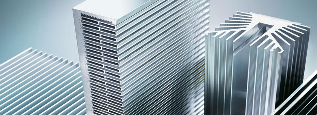
The lightness (2,7 g/cm3), the thermal conductivity (220 W/m*K) and the malleability are the main properties making aluminium the most suitable metal for our heat dissipation systems. If not otherwise stated, the characteristics of used extruded profiles are:
- Chemistry composition: Aluminium Alloy EN AW-6060, 6061, 6063 or 6082, according to EN 573-3 European regulation
- Mechanical characteristic: T5 or T6, according to EN 755-2 European regulation
- Tolerances on dimensions and form according to EN755-9 European regulation
Specials
Mecc.Al manufactures and supplies the following mechanical product variations for the electronic industry:
- Extruded commercial profiles (flat bars, angles, square bars, L and U profiles)
- Extruded boxes and cases
- Enclosures for high frequency technology made from a full aluminium profile
Schedule a speed date for more information
Do you have any product or application specific questions about air cooled heatsinks? Please schedule a short speed date with one of our specialists.
Schedule a Technical Online Meeting with Aniket
We offer a technical online meeting as an extra service to get to know you and your business. If you have any DC related questions, need help with your power electronics projects or if you are looking for support with complex power electronics related challenges, our technical meeting will be of value. Schedule your desired time slot below!