Modern data centers face unexpected power failures despite being fully compliant. This new whitepaper explores how spectral impedance measurement turns hidden system interactions into measurable operational intelligence to secure uptime.
Turning Hidden Power-System Interactions into Measurable Operational Intelligence
Modern data centers are among the most electrically dense and operationally critical infrastructures in the world. Their power systems combine utility feeds, transformers, UPS systems, generators, battery systems, switchgear, power distribution units, and thousands of switched-mode power supplies. Each of these components may be compliant with applicable power quality, grid, and EMC standards when evaluated individually. Yet in real-world operation, the interaction between these devices can still lead to unexpected failures, instability, excessive noise, overheating, harmonic amplification, stray currents, and premature degradation.
Traditional power quality assessments typically focus on observable voltage and current phenomena: harmonics, flicker, unbalance, sags, swells, interruptions, transients, and frequency deviations. These measurements are important, but they often describe the symptoms rather than the underlying system behavior. Spectral impedance measurement adds a missing layer: it reveals how the electrical infrastructure responds across frequency. In other words, it makes the “invisible” electrical characteristics of the grid measurable.
For data center operators, this is not merely an engineering refinement. It is a risk-management capability. Spectral impedance measurement can help identify resonance conditions, detect degraded filters, assess grid-state changes, uncover common-mode current paths, and support better decisions about equipment integration, expansion planning, commissioning, and predictive maintenance. As data centers continue to scale in power density and operational complexity, understanding spectral impedance becomes a practical requirement for improving resilience, uptime, and asset lifetime.
The Challenge: Compliance Does Not Guarantee Compatibility
A recurring problem in modern electrical systems is the gap between regulatory compliance and operational compatibility. A power supply unit may satisfy grid-compliance and EMC requirements in isolation. A data center electrical infrastructure may be designed to support the required power demand. On paper, both sides appear acceptable. In practice, however, the interaction between nonlinear electronic loads and the surrounding electrical network may create conditions that were not visible during certification or design review.
This distinction is especially relevant in data centers because the load profile is dominated by power electronics. Switched-mode power supplies, UPS systems, inverters, rectifiers, and battery converters are not purely linear loads. They do not simply consume power at the fundamental grid frequency. Instead, they can introduce broadband spectral current components into the system. When these currents encounter frequency-dependent grid impedance, they can generate voltage harmonics, oscillations, or resonance effects.
The resulting failures may appear unrelated: PSU failures, transformer stress, generator instability, battery malfunctions, arcing in switchgear, or unexplained electromagnetic interference. Conventional measurements may confirm that the installation remains within regulatory limits, while the actual system continues to experience stress. This is why data center power quality must be evaluated not only by what is present in voltage and current waveforms, but also by how the system behaves across the frequency spectrum.
What Spectral Impedance Measurement Adds
Spectral impedance describes impedance as a function of frequency. Instead of treating the grid or internal distribution system as a static equivalent impedance, it characterizes how the system responds at many frequencies. This is critical because modern data center power systems operate in an environment where high-frequency effects, switching frequencies, harmonics, and oscillations can materially affect reliability.
Spectral impedance measurement provides three major categories of insight:
Device impedance reveals how individual equipment behaves electrically across frequency. It can expose degraded input filters, control-loop interactions, harmonic absorption or amplification, and conditions that may contribute to controller instability.
Grid impedance shows how the data center electrical infrastructure distributes spectral power. It is influenced by transformers, cabling, busbars, grounding structures, connected loads, generators, UPS systems, and operating topology. Because it is location-dependent and time-dependent, it is difficult to predict accurately through simulation alone.
Common-mode impedance helps identify how unwanted currents may flow through grounding systems, metal structures, cabinets, protective earth connections, or unintended conductive paths. This is important for understanding stray currents, electromagnetic coupling, and unpredictable interference mechanisms.
Together, these measurements create a more complete picture of the electrical environment. They allow operators to move from reactive troubleshooting to proactive system understanding.
Why This Matters for Data Center Reliability
The business impact of electrical instability in a data center can be severe. Even small disturbances may cascade into larger reliability concerns if they affect UPS behavior, power supply lifetime, monitoring systems, or switchgear performance. Spectral impedance measurement helps reduce this risk in several practical ways.
First, it improves root-cause analysis. When failures occur despite apparent compliance, operators need a method to identify whether the cause is device degradation, grid resonance, poor damping, common-mode coupling, or an interaction between multiple systems. Spectral impedance data provides a technical basis for distinguishing between these scenarios.
Second, it supports predictive maintenance. For example, degraded filters in power supplies or converters can change the spectral signature of a device. Measuring device impedance can reveal these changes before they result in widespread failures. In environments with many similar PSUs, this enables comparison across units and helps identify outliers that inject more noise into the grid or place additional stress on neighboring equipment.
Third, it strengthens commissioning and integration. Adding new UPS systems, generators, battery storage, high-density racks, or DC distribution elements can change the impedance profile of the facility. A system that was stable before expansion may become vulnerable to resonance after topology changes. Spectral impedance measurement provides a before-and-after view that can validate whether new equipment is electrically compatible with the existing infrastructure.
Fourth, it enables better planning for AC and DC architectures. The same principle applies to both. In AC systems, the concern may appear as harmonics. In DC systems, similar phenomena can appear as oscillations around the DC operating point. As data centers increasingly evaluate hybrid AC/DC architectures, battery-integrated systems, and converter-dense topologies, impedance-based analysis becomes a common language for both environments.
From Measurement to Management
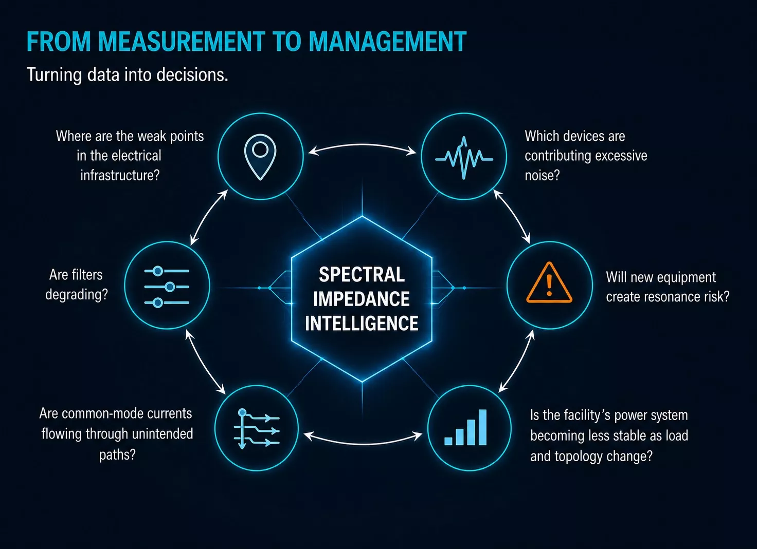
The key advantage of spectral impedance measurement is that it converts hidden system behavior into actionable operational intelligence. It shows where resonances exist, how impedance changes over time, and which parts of the infrastructure are more vulnerable to spectral current injection. This helps engineering teams and decision makers answer practical questions:
Where are the weak points in the electrical infrastructure? Which devices are contributing excessive noise? Are filters degrading? Will a new equipment cluster create resonance risk? Are common-mode currents flowing through unintended paths? Is the facility’s power system becoming less stable as load and topology change?
These questions matter not only to electrical engineers, but also to executives responsible for uptime, capital investment, energy infrastructure, and operational risk. The value of spectral impedance measurement lies in bridging these perspectives. It offers technical depth while supporting business decisions around reliability, maintenance prioritization, asset protection, and capacity expansion.
Business Benefits
For data center owners and operators, the primary benefits can be summarized in five areas:
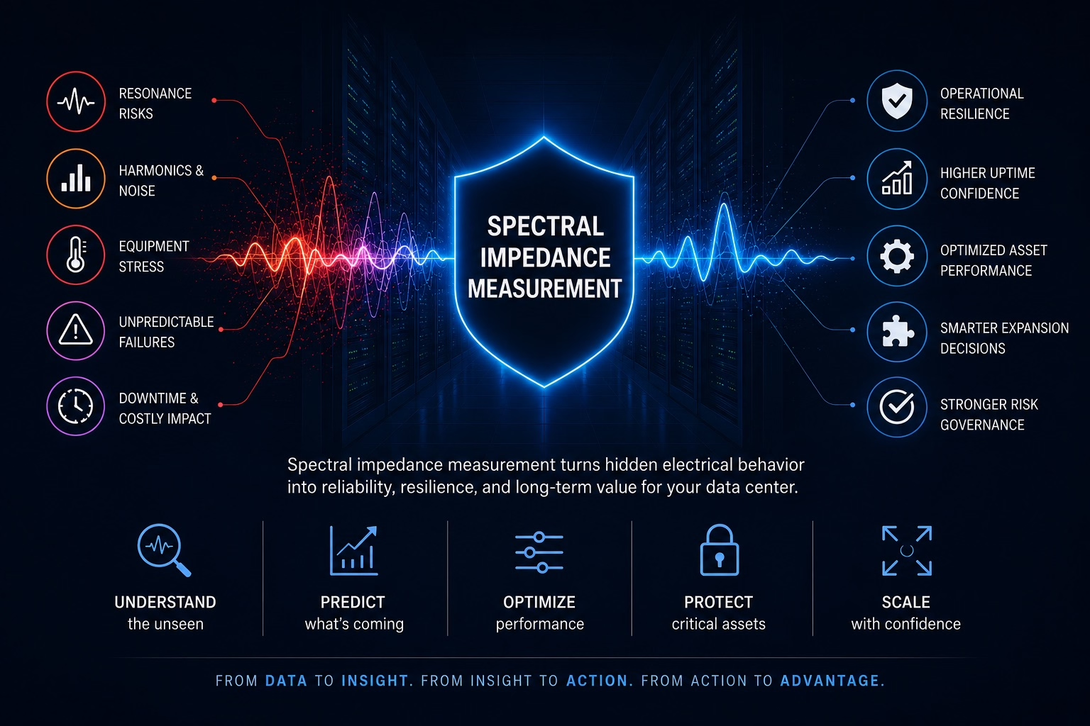
Higher uptime confidence. By detecting electrical interaction risks before they become failures, spectral impedance measurement supports a more resilient operating model.
Reduced troubleshooting time. Instead of treating symptoms individually, teams can identify the underlying impedance-related mechanism that connects noise, harmonics, oscillations, or device stress.
Improved asset lifetime. Early detection of degraded filters, resonance exposure, and excessive spectral loading can reduce avoidable stress on PSUs, UPS systems, generators, transformers, and switchgear.
Better expansion decisions. Measurement-based impedance profiles help evaluate whether new equipment can be integrated safely into the existing electrical environment.
Stronger risk governance. Spectral impedance data provides objective evidence for maintenance planning, vendor discussions, commissioning validation, and operational decision-making.
Conclusion
Data centers are no longer simple electrical loads. They are complex, converter-rich ecosystems in which thousands of devices interact through a shared power infrastructure. Regulatory compliance remains essential, but it is not sufficient to guarantee stable real-world operation. The missing variable is often spectral impedance: the frequency-dependent behavior of devices, grids, and common-mode paths.
Spectral impedance measurement gives operators the ability to visualize and quantify that hidden behavior. It complements conventional power quality analysis by explaining why certain harmonics, oscillations, failures, or interference patterns occur. For technical teams, it is a diagnostic and predictive tool. For business leaders, it is a way to reduce operational risk, protect critical assets, and improve confidence in data center scalability.
In a market where uptime, efficiency, and infrastructure resilience directly affect competitiveness, spectral impedance measurement should be considered a strategic capability for next-generation data center power management.

Frequently Asked Questions (FAQ)
Conventional power quality monitoring primarily measures what is present in the electrical system, such as voltage harmonics, current harmonics, flicker, unbalance, transients, sags, swells, and frequency deviations. Spectral impedance measurement adds information about how the electrical system itself responds at different frequencies.
This distinction becomes important when investigating interactions between power-electronic devices and the surrounding network. A harmonic voltage, for example, may not simply be the result of excessive harmonic current. It may be amplified because the network impedance is relatively high at that particular frequency.
By measuring impedance as a function of frequency, engineers can distinguish more effectively between the disturbance source and the electrical conditions that amplify or suppress that disturbance.
Compliance testing evaluates equipment under defined test conditions and against specified emission, immunity, grid, and safety limits. These conditions cannot represent every electrical environment in which the equipment will eventually operate.
In a data center, many converters, UPS systems, power supplies, filters, transformers, cables, and other components operate simultaneously and are coupled through a common electrical infrastructure. Their combined frequency-dependent characteristics can create interactions that are absent during individual equipment testing.
As a result, two compliant subsystems can still interact unfavorably. This is why compliance should not automatically be interpreted as proof of system-level electrical compatibility.
The impedance of an electrical network is not constant with frequency. Transformers, cables, capacitors, filters, UPS systems, generators, and connected loads all contribute inductive, capacitive, and resistive characteristics that shape the network impedance.
At certain frequencies, these characteristics can produce impedance peaks or resonant conditions. If equipment injects spectral current near such a frequency, even a relatively modest current component can produce a disproportionately large voltage disturbance.
Spectral impedance measurement allows engineers to identify these frequency-sensitive regions and evaluate whether existing or planned loads are likely to excite them.
Simulation remains extremely valuable, particularly during design and system studies, but its accuracy depends on the quality of the underlying component models and assumptions.
Real installations contain effects that can be difficult to model completely, including cable parasitics, changing load populations, control behavior of converters, aging components, grounding structures, filter tolerances, switching configurations, and undocumented modifications.
In addition, the effective impedance seen from a particular point in the installation can change with operating state. Measurement therefore complements simulation by showing the actual frequency-dependent behavior of the installed system under real operating conditions.
Potentially very location-dependent. The impedance observed at a utility interface, UPS output, main distribution bus, PDU, or individual rack can differ significantly because each measurement point sees a different combination of upstream and downstream electrical components.
This means that a resonance visible at one point may be much less pronounced elsewhere, while another local resonance may appear closer to the load.
For practical diagnostics, the measurement location therefore matters. Comparing impedance profiles at several strategically selected points can help engineers determine where an interaction originates and how it propagates through the distribution system.
Potentially, particularly when measurements can be compared against a known baseline or against a population of electrically similar devices.
Aging capacitors, damaged filter components, component drift, or other degradation mechanisms can alter the frequency-dependent input impedance of a PSU or converter. These changes may become measurable before the device reaches complete functional failure.
The diagnostic value becomes especially interesting in large homogeneous populations. Instead of relying only on absolute thresholds, engineers can compare devices and identify impedance signatures that deviate from the normal population, providing an additional indicator for condition-based maintenance.
This requires looking at both sides of the interaction. Measuring only harmonic current may suggest that a load is responsible, while measuring only voltage distortion may suggest that the network is problematic. Neither observation alone necessarily identifies the mechanism.
By combining voltage and current measurements with device and grid impedance information, engineers can determine whether a disturbance is primarily caused by excessive spectral current injection, an unfavorable network impedance, or an interaction between the two.
This distinction is particularly valuable during root-cause analysis because the appropriate corrective action may be completely different: modifying a load, changing filtering, adding damping, or altering the network topology.
The impedance profile can change substantially. Switching between utility and generator operation, changing UPS configurations, connecting or disconnecting capacitor banks or filters, transferring loads, or adding battery energy storage can alter the electrical network seen by connected equipment.
Consequently, a system may have acceptable impedance characteristics in one operating state but exhibit a resonance or reduced stability margin in another.
For critical facilities, this suggests that impedance should not necessarily be treated as a single static characteristic. Measurements across representative operating states can reveal risks that would otherwise remain hidden during normal operation.
UPS systems and generators introduce additional dynamic behavior into the electrical network. Their effective output impedance varies with frequency and can be influenced by control loops, filters, operating mode, load level, and other connected equipment.
During generator-backed operation, the electrical environment may therefore differ significantly from normal utility operation. An installation that behaves well when connected to a relatively stiff utility supply may behave differently when supplied by a generator with a different frequency-dependent impedance.
Measuring these states can help identify frequency regions where connected converters, UPS systems, and generation equipment may interact unfavorably.
Differential-mode and common-mode currents follow different electrical paths and can therefore be governed by very different impedances.
Common-mode currents may return through protective earth conductors, cabinets, cable shields, grounding structures, building steel, cooling infrastructure, or other unintended conductive paths. These paths are often difficult to represent accurately in simplified electrical models.
Measuring common-mode impedance can therefore provide insight into interference, stray-current behavior, unexpected coupling between systems, and other phenomena that may not be explained by conventional phase-to-phase or phase-to-neutral measurements.
A useful approach is to establish impedance profiles at selected electrical nodes during commissioning and use them as reference measurements for future changes.
When a major new load cluster, UPS, generator, battery system, PDU, or converter-based subsystem is introduced, measurements can be repeated and compared with the baseline. Engineers can then determine whether resonance frequencies have shifted, new impedance peaks have appeared, or damping has changed.
This creates a measurement-based method for evaluating electrical compatibility before and after infrastructure changes rather than relying exclusively on component specifications and steady-state load calculations.
The most useful information is generally not a single impedance value, but changes in the frequency-dependent impedance profile.
Engineers may track parameters such as resonance frequency, peak impedance magnitude, damping around resonant regions, phase behavior, broadband changes in device impedance, common-mode impedance, and deviations between comparable equipment.
When these measurements are correlated with topology, load level, equipment age, maintenance activity, temperature, and power quality events, spectral impedance can evolve from a diagnostic measurement into an operational condition indicator. The objective is not simply to detect that impedance has changed, but to determine whether that change represents increasing electrical interaction risk.