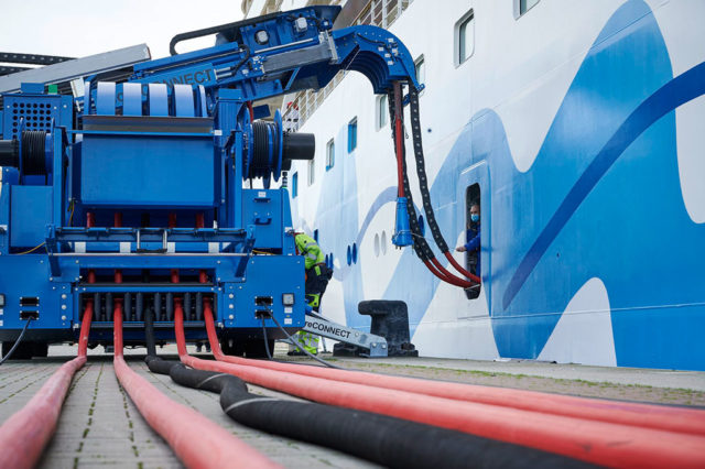
A practical guide to resistive load banks, high-power resistors, load-step control and MW-scale microgrid testing.
What is a load bank and how does it work?
A load bank is essentially a controllable “artificial electrical consumer.” Instead of connecting a generator, converter, battery system, or electrical distribution system to its normal operational loads, you connect it to a load bank and deliberately make it consume a known amount of electrical power.
For testing and commissioning of (micro)grids, this is extremely useful because you can create repeatable, controlled load conditions without requiring the actual operational loads. This article focuses on resistive load banks; for AC testing, load banks can also include inductive and/or capacitive sections when reactive power and power factor need to be reproduced.
The basic principle
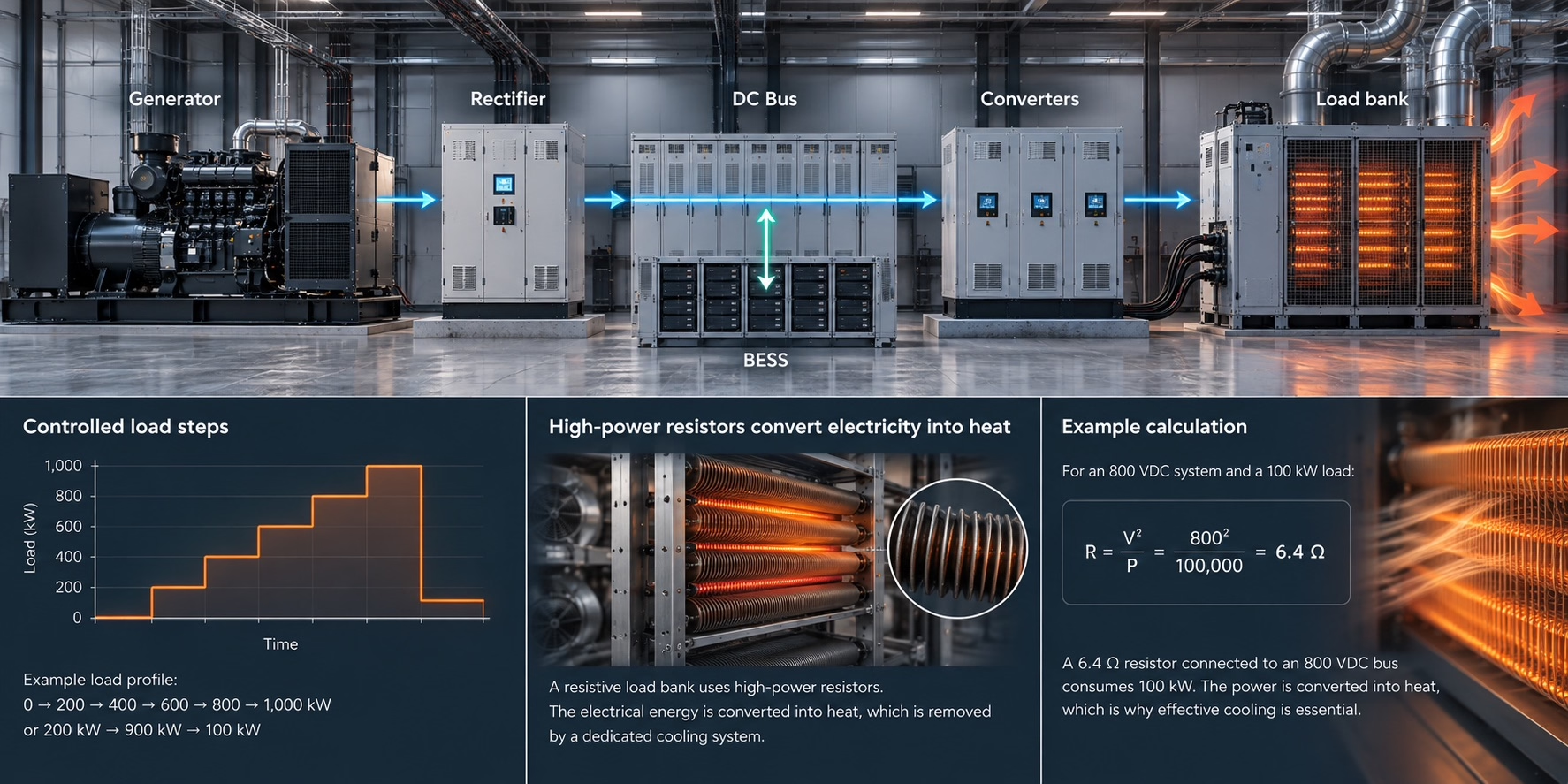
Imagine a 1 MW DC microgrid consisting of a generator, rectifier, DC bus, battery and converters:
Generator → Rectifier → DC Bus → Loads
↕
BESS
During commissioning you may want to know:
- Can the system continuously deliver 1 MW?
- What happens if the load suddenly jumps from 200 kW to 800 kW?
- Does the DC-bus voltage remain stable?
- Does the battery respond correctly?
- Does the generator controller react correctly?
- Do protection and control systems respond correctly to load changes?
- Does the cooling system cope with full load?
Instead of installing the actual loads, you connect:
Generator → Rectifier → DC Bus → LOAD BANK
The load bank can then be commanded, for example:
0 → 200 → 400 → 600 → 800 → 1,000 kW
or even:
200 kW → 900 kW → 100 kW
This allows engineers to study the dynamic response of the complete system.
High-power resistors: the heart of a resistive load bank
A very simple electrical load can be made with a resistor.
From Ohm’s law:

and therefore:
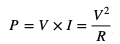
Suppose you have an 800 VDC microgrid and want to create a 100 kW load. Such voltage levels are being introduced in next-generation AI data-center architectures.
You need:
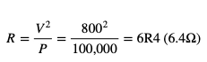
So, a 6R4 resistor connected to an 800 VDC bus consumes: 100 kW
The electrical energy doesn’t disappear. The resistor converts practically all of it into heat. Because the resistance is fixed, however, the absorbed power varies approximately with the square of the applied voltage.
That is why cooling is such an important part of load-bank design.
Why use multiple resistors?
A useful load bank normally does not contain just one large resistor. Instead, it is divided into several independently switched resistor sections or load stages.
The important point is not simply to divide the total power into equal sections. By carefully selecting the power rating of each resistor section, many different load levels can be created with a relatively small number of resistors.
For example, a 2.2 MW load bank designed for 50 kW resolution could contain:
| Stage | Load |
| 1 | 50 kW |
| 2 | 100 kW |
| 3 | 200 kW |
| 4 | 400 kW |
| 5 | 650 kW |
| 6 | 800 kW |
| Total | 2,200 kW |
Each resistor section is switched independently by a suitably rated contactor or semiconductor switching device. By combining these sections, the controller can create every load level from 0 to 2.2 MW in steps of 50 kW.
0 → 50 → 100 → 150 → 200 → 250 kW → … → 2.2 MW
This means that only six independently switched resistor sections are required to create 45 different load levels, including zero.
If 100 kW resolution is sufficient, the number of sections can be reduced even further. A 2.2 MW load bank could, for example, use:
100 + 200 + 400 + 700 + 800 kW
These five sections can generate every load level from 0 to 2.2 MW in 100 kW increments.
This illustrates an important part of load-bank design: the resistor ratings should be selected according to both the required maximum power and the required load-step resolution. A well-chosen combination can provide many controllable load levels without requiring many separate resistor assemblies.
This modularity is one of the reasons the choice and configuration of the high-power resistors is so important. Astrolkwx specializes in advising customers on selecting the appropriate resistor technology, resistance values and power ratings for the required load-bank architecture.
What is inside a load bank?
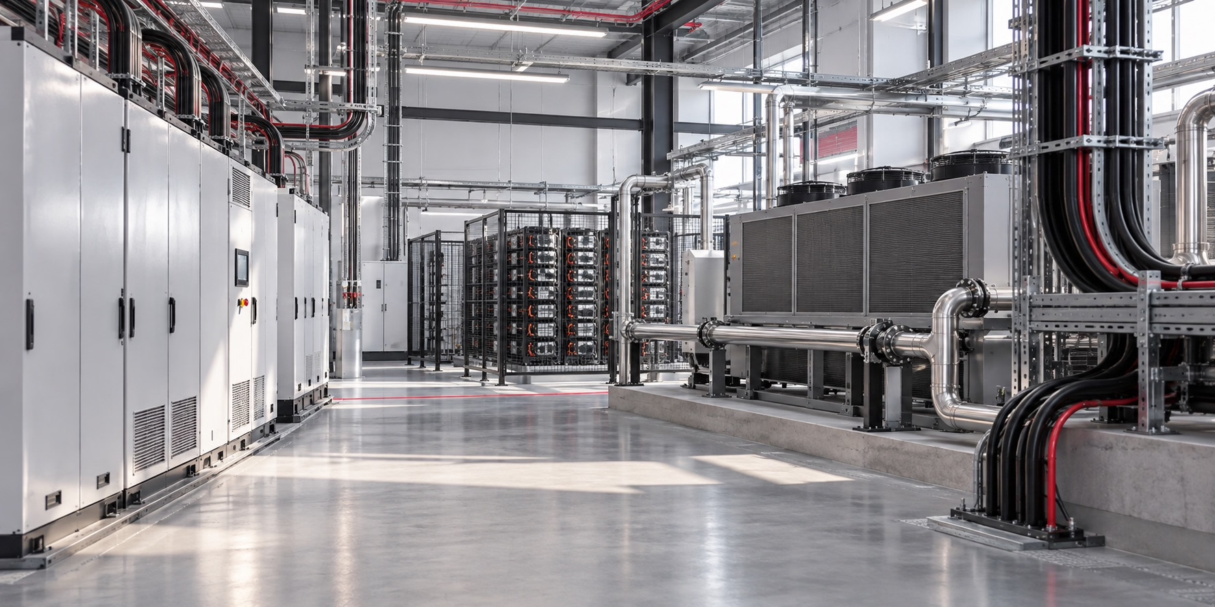
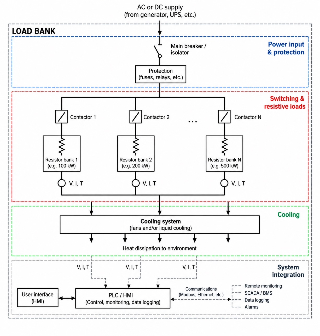
A simplified resistive load bank looks like this image.
There are therefore several major building blocks: the power resistors, switching devices, protection, measurement, controller and cooling system.
But in a resistive load bank, the resistors are ultimately the components absorbing the electrical power.
Why high-power resistor design and quality matter?
It might sound simple: we just need something that gets hot.
Designing a reliable MW-scale load bank around resistors requires careful engineering, considering thermal capability, resistance value and stability, and voltage capability.
Thermal capability
A 2.2 MW resistive load bank operating at full power generates approximately 2.2 MW of heat. After one hour, this corresponds to 2.2 MWh of thermal energy, almost all of which must be dissipated through the cooling system.
The resistor manufacturer must therefore specify the permitted load profile. For example, a resistor may be rated for continuous operation at 100 kW under specified cooling and ambient conditions, or for a temporary overload of 150 kW for 60 seconds. These represent very different thermal duties.
Resistance stability
As a resistor becomes hot, its resistance typically changes to some extent.
At a fixed bus voltage, if resistance increases significantly:

the actual load decreases.
For a test system this can be undesirable because you may command a nominal 500 kW load, but after the resistor bank becomes hot it could absorb somewhat less.
A good high-power resistor therefore needs an appropriate resistance tolerance (5% or 3%), temperature coefficient of resistance (100 ppm/K or less) and thermal design so the load remains predictable.
Voltage capability
The insulation and physical resistor construction also must withstand the system voltage. For an 800 or 1,500 VDC microgrid, for example, engineers must consider much more than the kW rating:
Creepage and clearance distances, insulation coordination, terminals, eddy currents, transient voltages and, where fast switching is relevant, parasitic inductance all matter. Our experts can advise on these aspects.
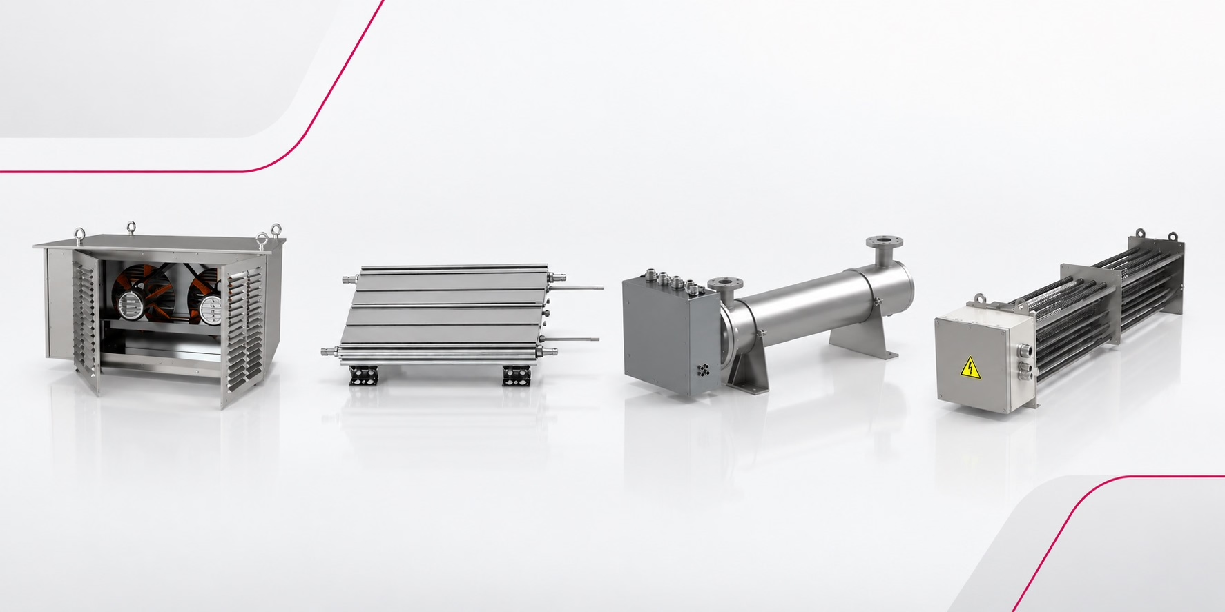
Explore our range of high power resistors
Load-step resolution and grid simulation
The required load-step resolution depends on the purpose of the test. A load bank intended mainly for full-load testing may only require relatively large steps. A load bank used for microgrid development or dynamic testing may require much finer control. By selecting the resistor sections carefully, fine resolution does not necessarily mean that many resistor banks are required.
For example, the six-section 2.2 MW load bank described above can generate any load between 0 and 2.2 MW in 50 kW increments.
A programmed test profile could therefore be:
| Time | Load |
| 0 sec | 100 kW |
| 10 sec | 300 kW |
| 20 sec | 750 kW |
| 21 sec | 1,600 kW ← sudden load step |
| 30 sec | 2,200 kW |
| 45 sec | 500 kW |
| 46 sec | 50 kW ← sudden load rejection |
Instead of simply testing whether the power supply can deliver 2.2 MW, the load bank can therefore reproduce controlled load changes with a known and repeatable step size. This allows engineers to study how the complete microgrid responds to both steady-state loading and rapid changes in power demand.
Why are load banks particularly useful for DC microgrids?
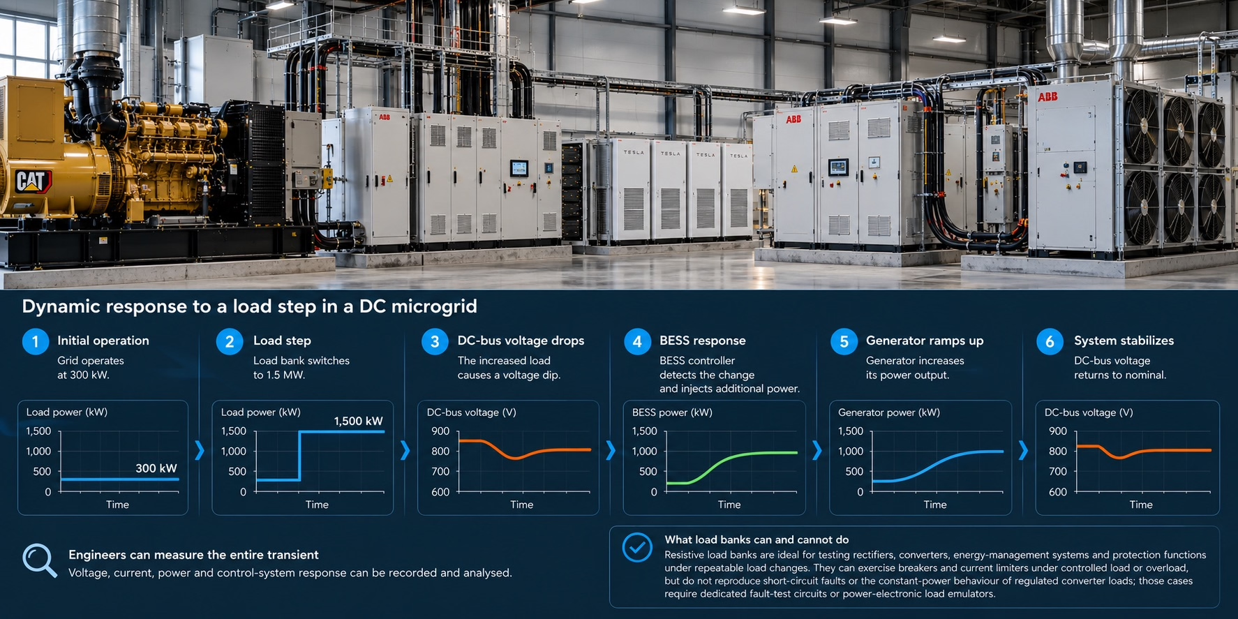
Modern DC microgrids are found in ships and BESS installations and are emerging in 800 VDC data-center architectures. A programmable resistive load bank can apply known, repeatable load steps to the DC bus.
For example, you could test a system configured so that:
- The grid operates at 300 kW.
- The load bank is switched to a nominal 1.5 MW load at rated voltage.
- The DC-bus voltage starts to fall.
- The BESS controller detects the change.
- The battery injects additional power.
- The generator ramps up.
- The DC bus stabilizes.
- Engineers can measure the entire transient.
Resistive load banks are useful for evaluating rectifiers, converters, energy-management systems and protection functions under repeatable load changes. They can exercise breakers and current limiters under controlled load or overload, but do not reproduce short-circuit faults or the constant-power behaviour of regulated converter loads; those cases require dedicated fault-test circuits or power-electronic load emulators.
Air-cooled versus liquid-cooled resistors
This becomes a major design decision at high powers.
Forced-air-cooled resistors
The common architecture is approximately:
Resistor elements → airflow → large fans → hot air exhaust
Compared with liquid cooling, the advantages are relative simplicity and robustness.
The disadvantage is obvious at MW scale: enormous amounts of hot air must be moved.
Liquid-cooled resistors
With liquid-cooled high-power resistors:
Electrical power → resistor → cooling liquid → heat exchanger
Liquid cooling can make the resistor assembly much more compact, especially where a suitable cooling-water circuit already exists, but it requires pumps, piping, heat exchangers, coolant monitoring and leak-management provisions.
Example of a complete load bank
A complete resistive load bank combines power resistors with switching, cooling, protection, measurement and control systems. The surrounding components determine when and how much load is applied, while the resistor elements convert the tested system’s electrical output into heat.
For a high-quality microgrid test load bank, the most important resistor-related parameters are:
- Continuous power rating and duty cycle
- Resistance value and tolerance
- Temperature coefficient
- Overload and pulse capability
- Operating voltage and insulation
- Cooling requirements
- Thermal cycling and lifetime
- Environmental robustness
- Resistor-bank segmentation and controllable load steps
Danotherm high-power resistors for load banks
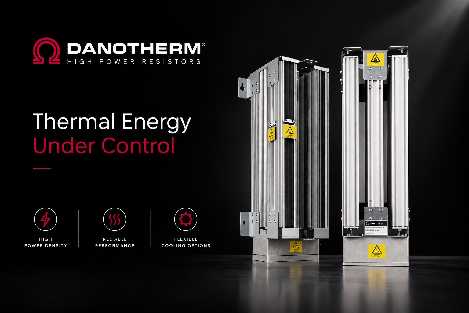
Danotherm Electric A/S high-power resistors are particularly suitable as the power-absorbing elements at the heart of resistive load banks.
A load bank needs resistor elements that can reliably absorb large amounts of electrical energy and convert this energy into heat, often continuously and under demanding load cycles. Danotherm offers resistor technologies covering natural air cooling, forced-air cooling and liquid cooling, allowing the load-bank designer to select the most appropriate solution depending on power density, available space, duty cycle and cooling infrastructure.
Natural-air-cooled resistors
Natural-air-cooled resistors are an attractive solution when simplicity, reliability and low maintenance are important. Heat is dissipated through convection without requiring dedicated fans or pumps. They are particularly useful for lower continuous power densities, pulse-duty applications, or installations where sufficient physical space and natural airflow are available.
Discover our natural-air-cooled power resistors
Forced-air-cooled resistors
Forced-air-cooled Danotherm resistors allow considerably more power to be dissipated from a compact resistor assembly. Fans force air across the resistor elements, carrying away the generated heat. Multiple resistor modules can be assembled into separately switched branches, making it possible to build load banks with controllable nominal steps such as 50, 100, 200 or 500 kW at rated voltage. This architecture can be scaled into MW-class load banks.
Discover our forced-air-cooled power resistors
Liquid-cooled resistors
For applications requiring very high-power density, liquid-cooled Danotherm resistors become especially interesting. The heat generated in the resistor is transferred directly into a cooling circuit rather than first having to heat a large volume of air. This can significantly reduce the resistor installation volume and is especially attractive in applications such as marine DC grids, BESS test systems, converter test benches and other high-power microgrid laboratories.
Discover our liquid-cooled power resistors
The basic principle is simple:
Electrical energy from the system under test → Danotherm resistor → heat → cooling system
The sophistication lies in controlling that process accurately and reliably. For example, instead of designing one enormous 2 MW resistor assembly, a load-bank manufacturer can combine multiple Danotherm resistor assemblies:
By switching these resistor sections independently, the load-bank controller can generate both steady-state resistive loads and rapid load steps. That makes it possible to apply repeatable changes in nominal power demand and study how generators, converters, batteries, DC buses and protection systems respond.
Resistor selection matters
This also explains why choosing the resistor technology is much more important than simply specifying “we need a 2 MW load bank.”
The resistor technology and bank configuration determine important characteristics of the finished system: maximum continuous power, power density, physical dimensions, cooling demand, achievable load-step resolution, thermal behaviour, overload capability and long-term reliability.
For a microgrid test facility, reliability under repeated thermal cycling can be particularly important. A load bank may repeatedly cycle:
0% → 25% → 75% → 100% → 20% → 100% → 0% rather than simply operating continuously at one load.
This is exactly where industrial high-power resistor technology becomes important: the resistor elements must tolerate repeated heating and cooling while maintaining predictable electrical and thermal behaviour.
Danotherm’s natural-air-cooled, forced-air-cooled and liquid-cooled resistor technologies enable load-bank designers to match power density, cooling, duty cycle and load-step requirements to the application. This makes them suitable for applications ranging from relatively simple load banks to compact MW-scale microgrid test systems.
More information? We are happy to advise you on selecting the correct resistor for your load-bank design.