AI is rapidly changing the electrical requirements of data centers. The most visible consequence is scale: more computing power requires more electrical power, driving higher rack densities and increasing the total capacity of data-center infrastructure.
But there is another development that is just as important for electrical system design: AI changes not only how much power is consumed, but also how that power is consumed.
The impact of AI training workloads on power demand
AI training workloads can create rapid and repetitive changes in power demand, including synchronized transitions between high and low power states across multiple GPUs. These variations can occur on millisecond and sub-second timescales. At the same time, the industry is moving toward higher-power DC architectures, with 800 VDC emerging as an important distribution voltage for next-generation AI infrastructure.
”The combination of highly dynamic loads, increasing power density and low-impedance DC distribution creates a new challenge for protection.”

Rethinking breaker selection for AI infrastructures
A solid-state DC breaker must be able to tolerate legitimate AI power peaks without unnecessary interruption, while still detecting, limiting and interrupting a genuine fault within microseconds.
This changes the way we should think about breaker selection. Instead of asking only “How much current must the breaker carry?”, electrical system designers also need to understand:
- How fast the load changes.
- How fast fault currents can rise.
- Which part of the DC grid needs to be isolated when something goes wrong.
AI dynamics vs. overloads: understanding the three current conditions
One of the most important distinctions in an AI data center is between three different current conditions. Recognizing these states has a direct impact on breaker sizing:
- Normal AI dynamics: Repetitive changes in current caused by the expected computing workload. The DC breaker should tolerate them without entering an overload timer.
- Temporary overload: An abnormal but permissible operating condition for a limited period, for example during load redistribution or controlled ride-through.
- Genuine short circuit: A critical fault requiring immediate detection, current limiting and interruption on a microsecond timescale.
The electrical reality of DC breaker sizing
This distinction has a direct impact on breaker sizing.
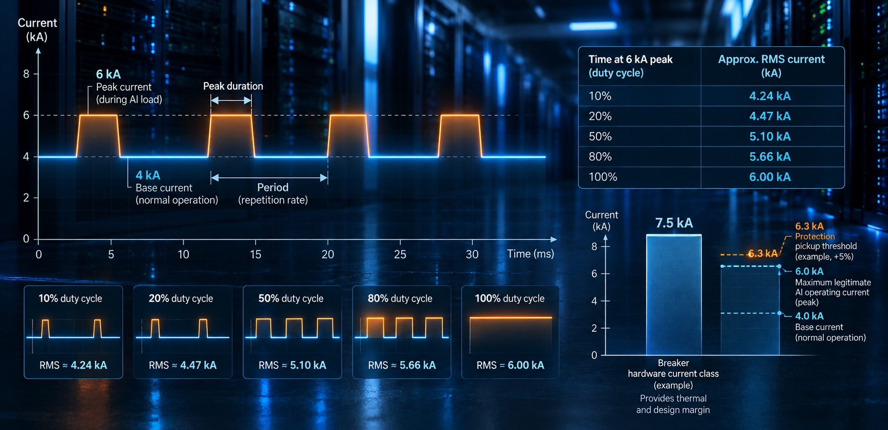
Consider an illustrative 800 VDC system with a base current of 4 kA and repetitive AI dynamics of +50%:
4 kA × 1.5 = 6 kA peak current
Now consider a 5 kA breaker with 20% temporary overload capability:
5 kA × 1.2 = 6 kA
Mathematically, the numbers match perfectly; electrically, they may not.
- The overload risk: If the 20% capability is designed for occasional overload lasting seconds or minutes, it cannot automatically be interpreted as permission to operate repeatedly at 6 kA.
- Component fatigue: A DC breaker frequently cycling between 5 and 6 kA could spend a substantial part of its operating life in a region intended only for temporary operation.
For AI applications, the maximum legitimate repetitive peak should therefore be part of the normal breaker operating envelope.
Distinguishing peak current from thermal loading: the role of RMS current
This does not mean that a breaker experiencing a 6 kA peak always needs to be thermally designed as if it continuously carries 6 kA. The thermal requirement depends strongly on how long and how frequently the peak occurs.
For the illustrative profile above, the calculated root-mean-square (RMS) current varies considerably with the AI peak duty cycle:
| Time at 6 kA peak (%) | Approx. RMS current (kA) |
| 10% | 4.24 kA |
| 20% | 4.47 kA |
| 50% | 5.10 kA |
| 80% | 5.66 kA |
| 100% | 6.00 kA |
The protection function must tolerate the legitimate instantaneous peak, while the semiconductor, cooling system and overall breaker design must tolerate the resulting RMS current and transient thermal stress.
Consequently, when selecting the right breaker, you must evaluate all the following parameters:
- Base current and peak current
- Peak duration and repetition rate
- Duty cycle
Separating hardware current ratings from electronic protection thresholds
Solid-state protection also allows an important distinction between the breaker’s hardware current class and its electronic protection threshold.
For the illustrative 4 kA base / 6 kA repetitive peak case, a 7.5 kA hardware class can be a logical engineering starting point to provide thermal and design margin.
But that does not mean the protection pickup should also be 7.5 kA.
Once the maximum legitimate AI operating current has been established, the protection threshold can be positioned much closer to that envelope. In this example, 5% additional headroom is used as an illustrative starting point:
6.0 kA × 1.05 = 6.3 kA pickup
This 5% is not a standard requirement. The appropriate value depends on several critical factors:
- Sensing tolerance and modelling uncertainty
- Current sharing between components
- The required availability philosophy
It is essential that the breaker needs sufficient hardware capacity to carry the AI load, while the protection should still react as early as reasonably possible to a genuine fault. And in low-inductance DC systems, such as data center architectures, that difference matters enormously.
High di/dt: the challenge of rapid fault current rise
Modern high-power DC architectures aim to minimize electrical losses and impedance. Future architectures may have extremely low-impedance connections between solid-state transformers, DC buses, energy storage and computing loads. While highly beneficial during normal operation, this low inductance poses a massive risk during a fault: the short-circuit current will rise extremely fast.
The initial current rise can be approximated by:
di/dt ≈ V/L
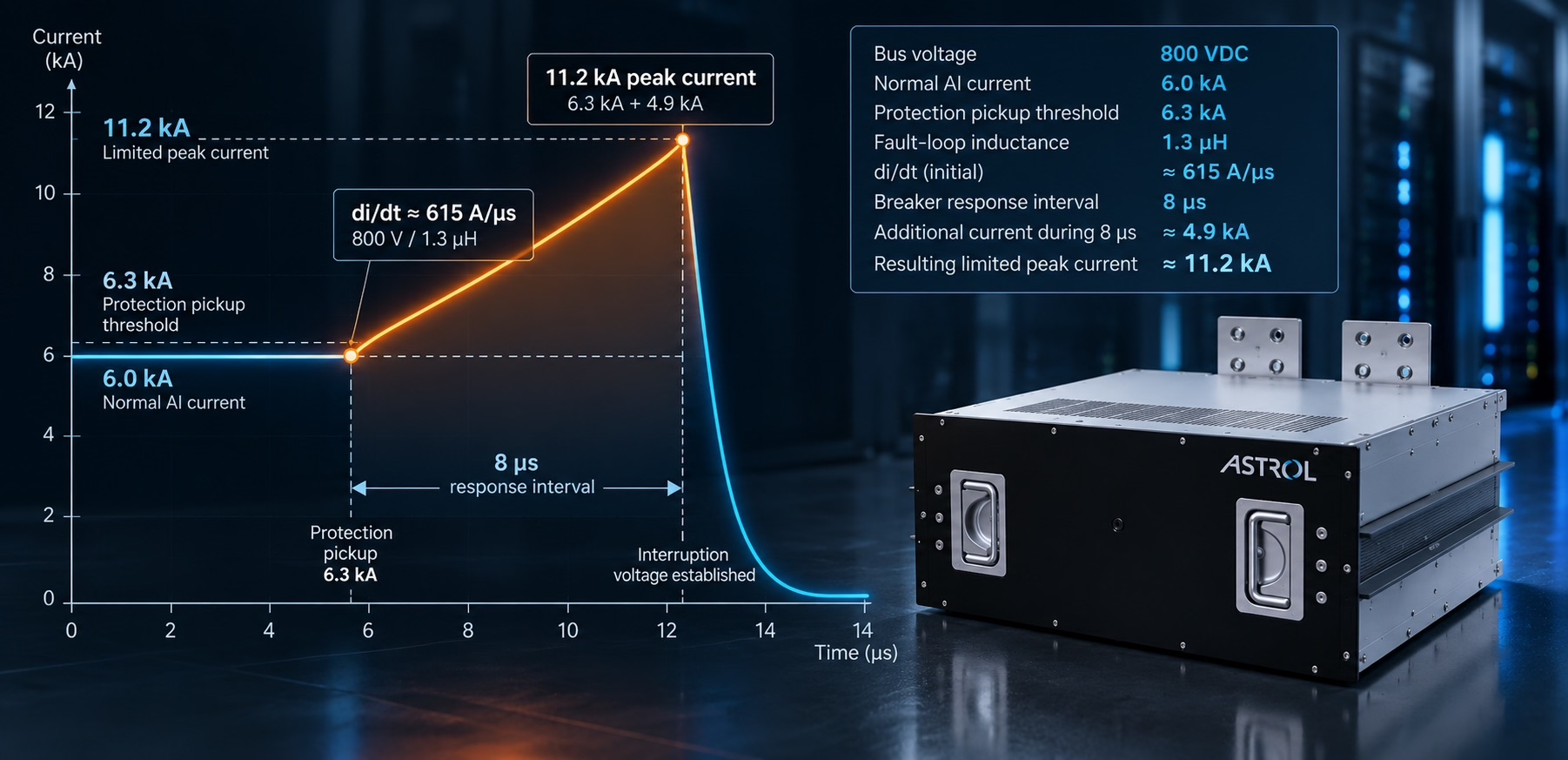
Consider an illustrative 800 VDC system with a total fault-loop inductance of only 1.3 µH:
800 V / 1.3 µH ≈ 615 A/µs
During this initial current-rise interval, every microsecond of protection delay corresponds to approximately 615 A of additional current. The compounding effect is severe:
- 5 microseconds: Adds around 3.1 kA of extra current.
- 8 microseconds: Adds around 4.9 kA of extra current.
Low inductance is highly attractive for efficient power distribution but exceptionally demanding for electrical protection. The protection system has very little time to react before the fault current reaches levels that can stress semiconductors, busbars, converters and other components.
Beyond prospective short-circuit current: the real metric for solid-state breakers
A traditional protection specification might state: ‘Prospective short-circuit current: 40 kA. That remains useful information, but it is not sufficient to select an ultra-fast solid-state DC breaker. Knowing how much current will actually develop before the breaker establishes the interruption voltage is essential.
As an example:
- Bus voltage: 800 VDC
- Maximum normal AI current: 6.0 kA
- Protection pickup threshold: 6.3 kA
- Total fault-loop inductance: 1.3 µH
- Breaker response interval: 8 µs
At approximately 615 A/µs, the current can increase by another 4.9 kA during the assumed 8 µs response interval (the time from pickup detection until the rising fault current is effectively arrested).
The resulting limited peak becomes:
6.3 kA + 4.9 kA = 11.2 kA peak current
The semiconductor and breaker architecture must therefore safely control a current significantly higher than both the normal operating current and the electronic pickup threshold.
Because of this dynamic behaviour, a comprehensive solid-state DC breaker selection must always evaluate:
- Fault-loop inductance and pre-fault current
- Exact detection time and response interval
- Semiconductor turn-off capability and Safe Operating Area (SOA)
- Clamping circuit design
System-wide protection: how current limiting safeguards infrastructure
The purpose of ultra-fast solid-state protection is not simply to disconnect a fault eventually. It is to prevent the fault current from developing toward its full prospective value.
By limiting the peak current, you significantly reduce the electrical and thermal stress experienced by the surrounding DC infrastructure, including:
- Busbars, cabling, and connectors
- Converters and semiconductor stages
- DC-link capacitors and energy-storage interfaces.
Current limiting should therefore be considered a system protection function, rather than only a characteristic of the circuit breaker.
Breaker vs clearing a fault
There is also an important difference between breaking a fault and completely clearing it.
After the semiconductor establishes the interruption condition, energy remains stored in the system inductance. The Metal Oxide Varistor (MOV) or another clamping and energy-absorption circuit must then establish a reverse voltage that drives the current to zero.
Consequently, total system clearance relies on a chain of tightly linked parameters:
- Detection time and semiconductor turn-off
- Clamp voltage and stored energy
- Total clearing time
Selectivity and zone protection in large-scale AI data centers
Fast interruption alone is not enough in a large AI data center. Consider an 800 VDC architecture with multiple computing loads, energy-storage systems and distribution branches connected to a common DC grid. If a fault occurs on one branch, shutting down the entire DC system may be unnecessary and undesirable.
Ideally, to guarantee maximum uptime, the intelligent protection system should execute the following sequence:
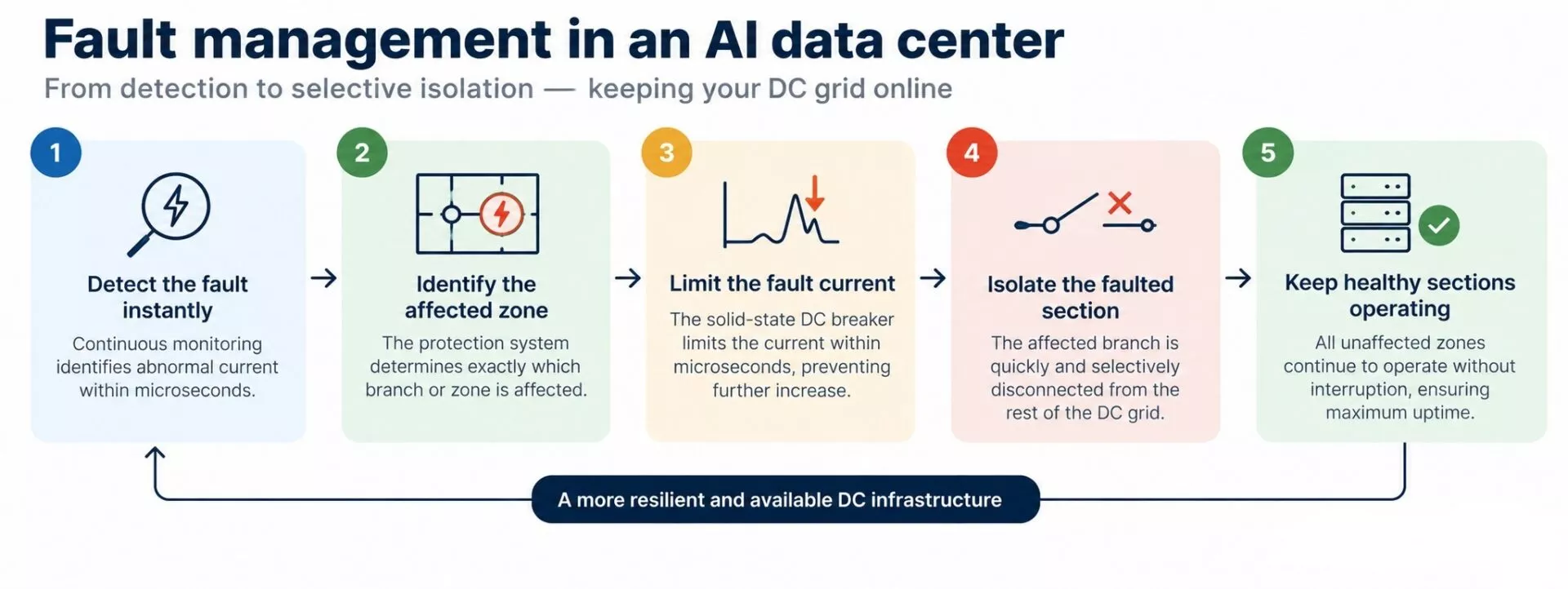
This makes selectivity and zone protection increasingly critical for next-generation data center engineering.
Achieving DC microgrid selectivity: from maritime vessels to AI data centers
At Astrolkwx our technical experts are highly skilled in advising on protection and achieving selectivity in DC microgrids.
The same principle is relevant in onboard DC power grids. This is an area in which we have extensive experience, with leading customers like Kongsberg Maritime. Read the success story: Kongsberg Maritime integrates solid-state DC breakers in CSOV vessel range – Read about our succes story – Astrolkwx
Traditional vs. Next-generation selectivity
Traditional protection systems often create selectivity through different current thresholds and intentional time delays. In a very-low-inductance DC network, however, deliberately waiting is no longer an option:
| Protection Approach | Mechanism | The AI data center / DC grid risk |
| Traditional Systems | Intentional time delays & current thresholds | Deliberately waiting allows fault currents to rise by hundreds of amperes per microsecond, overloading the breaker. |
| Next-Generation Systems | Fast local detection & coordinated logic | Fast communication between breakers and system topology isolates faults within microseconds without system stress. |
For next-generation DC architectures, selectivity must be engineered through a combination of:
- Ultra-fast local fault detection
- High-speed communication between breakers
- Coordinated protection logic and advanced system topology
Solid-state DC protection for 800 VDC AI infrastructure
At Astrolkwx and Astrol, we approach these challenges from the complete DC-system perspective.
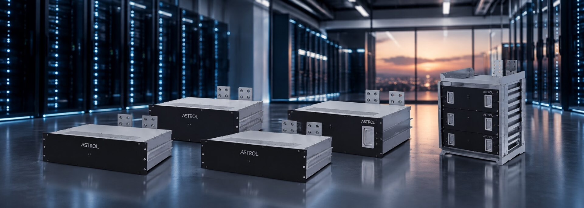
For 800 VDC applications, Astrol’s solid-state DC breaker platform offers various configurations to perfectly match different positions and load profiles within your architecture:
- Current classes: 500 A, 1 kA, 2.5 kA, 5 kA, and 7.5 kA
- Cooling options: Liquid-cooled and air-cooled designs
A main DC bus, an energy-storage connection and a downstream AI load feeder can all operate at 800 VDC while experiencing very different base currents, AI dynamics, fault-loop inductances and protection requirements. Solid-state switching enables ultra-fast current limiting, helping to interrupt the fault current, before it develops toward its full prospective value.
At the system level, communication and coordinated control between breakers can support selectivity and zone protection, with the objective of isolating the smallest practical faulted section while maintaining healthy parts of the DC grid whenever the architecture permits it.
Explore our range DC breakers for data centers
Your solid-state DC breaker selection checklist
To successfully protect next-generation AI infrastructure, your selection process must evaluate:
- The AI-load profile: Understanding base currents and repetitive peak dynamics.
- Hardware vs. protection: Matching the hardware current class while optimizing the electronic pickup threshold.
- System physics: Analyzing fault-loop inductance and pre-fault current.
- Breaker performance: Verifying response time, semiconductor turn-off capability, and current-limiting performance.
- Network position: Defining the breaker’s exact role within the overall protection architecture.
Conclusion: designing protection around the dynamics of AI
A solid-state DC breaker must tolerate legitimate repetitive AI peaks without unnecessary interruption. At the same time, once a genuine fault occurs, every microsecond can translate into hundreds of additional amperes of fault current. As DC architectures become larger and more interconnected, protection must do more than interrupt quickly. It must help determine where the fault is and which part of the system should be isolated.
This leads to three important design principles:
- The operating envelope: AI dynamics determine the normal boundaries of daily operation.
- The fault dynamics: System voltage and fault-loop inductance dictate how quickly the fault current develops.
- The DC architecture: determines how protection, selectivity and zone isolation should work together.
For next-generation 800 VDC data centers, solid-state breaker selection should therefore not start with voltage and current rating alone.
Effective DC protection is no longer about selecting a circuit breaker; it is about designing around the dynamics of the grid itself.
At Astrolkwx, we believe the ultimate engineering focus must therefore shift. Instead of evaluating components in isolation, we need to analyze how the complete DC system behaves during normal AI operation and how it responds in those first critical microseconds after a fault occurs.
Optimize your AI data center protection
Ready to bulletproof your next-generation power infrastructure against high di/dt faults? Our power electronics experts are here to help you achieve seamless selectivity.
Leave your contact details or schedule a technical online meeting with one of our power electronics experts.